Here are some photos of our revised front suspension.
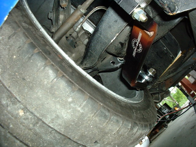
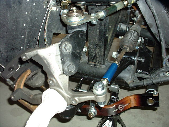
At right is our original installation, using the Mustang lower control arms.
The drop link attaches to a hole in the rear of the lower control arm. This was expedient, but didn't give us our target roll stiffness.
Below, we'll show
the final system, which comes very close to our target.

Here's another shot. You can see that the bar is mounted in pillow blocks bolted to the front of a 2 1/4" square tube, which is in turn bolted to the front of the 4" round frame tubes.
We abandoned this
method of mounting because the bar flexed too much and lost a
significant amount of the roll stiffness we designed for.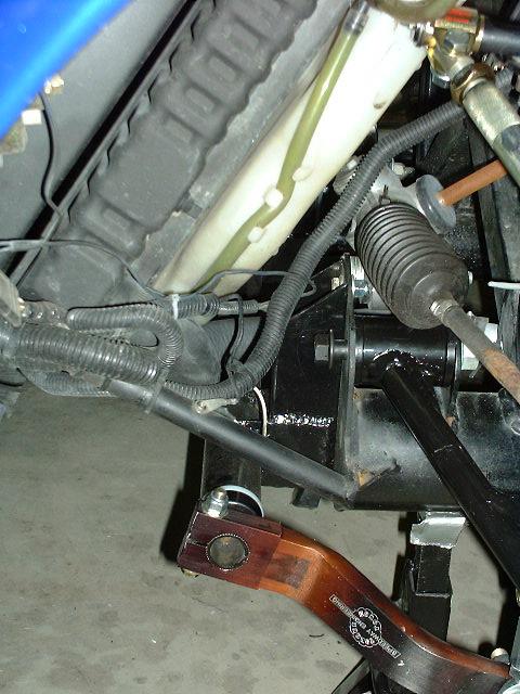
Here's the new mounting system.
Instead of the pillow blocks, the bar sits inside a tube, which has plastic bushings at the ends.
This way the bar is supported
all the way out to the end, so there is virtually no loss of
stiffness due to bending of the bar.
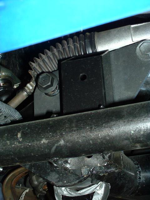
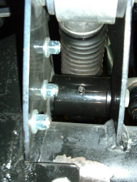
Here's a closeup of the bracket. The round steel tube is welded onto the front of the 2 1/4" square tube, which is in turn bolted to the frame.
Note the tab at lower right,
welded to the back of the square tube, which allows bolting the
bottom of the bracket to the side of the 4" round frame
tube. You can just see the bolt behind the tab.
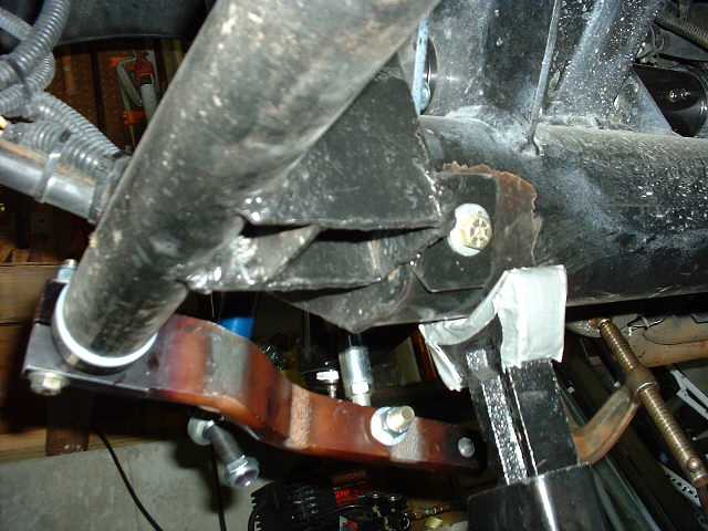
A shot of the bracket from below. Here you can clearly see the tab on the bottom of the bracket, and the bolt into the frame.
Nate drilled and tapped the
frame to match the threads of the bolt. Since the bolt is only
in shear, we figure this should hold.
This is looking in between the two plates that support the steering rack and the front of the lower control arm. The three bolts in the front plate (to the left) attach the top of the bracket to the frame.
We probably could have gotten
away with two bolts instead of three.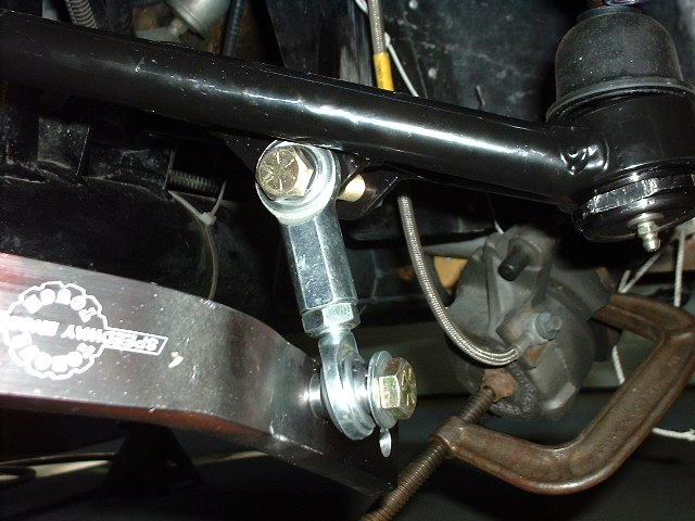
At right you can see the drop link, attached at the bottom to a hole in the arm, and at the top to the lower spring/shock mounting bolt.
This was a simple but expedient way to do this. All we needed was a longer bolt.
A better way would
be to weld a tab on the bottom of the lower control arm, as David Borden did. This allows you to choose
from several different stiffness settings.
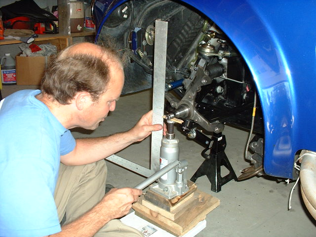
Here's Nate checking the wheel rate of the bar now that it's installed.
We blocked the other side with a two by four between the spring perches so it can't move up. Now he's jacking up the spindle with a jack on a bathroom scale, and measuring the weight on the scale at 1/4" intervals.
The rate turned out to be a
little lower than what we calculated, probably due to flexing
of the arms and brackets.
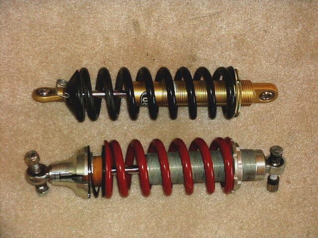
Here you can see the stock Pro Shock and spring (top) and the new Bilstein shock and spring. Note the machined aluminum "hat" on the bilstein, required to give proper clearance to the FFR control arms.
This hat is needed
both front and rear if you have FFR front lower control arms,
but it's not needed at the front if you are using the Mustang
arms and FFR lower shock brackets.
Here's a shot of the right front suspension, mostly back together.
The blue anodized aluminum thingie is part of the FFR bump steer kit.
To get the bump steer right,
we had to put the ball joint on the top of the control arm, and
raise the steering rack by flipping the eccentric bushings we
had previously used for mounting it.
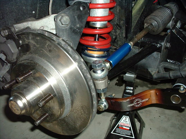
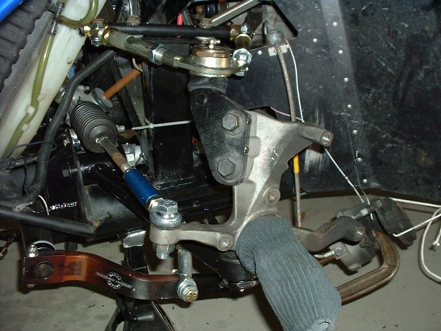
Another shot of the right side,
with spring and shock unit and brake installed.
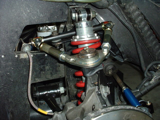
Here's the top of the spring and beefy Bilstein shock.
This is also a great view of the excellent FFR competition upper control arm. This does away with the need to slide the upper control arm mounting bolts in the slots in order to adjust camber and caster.
Rumor has it that these arms
will be standard on new kits.
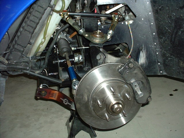
...with brake rotor and caliper.