|
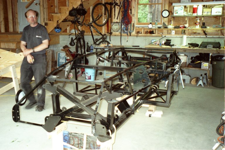
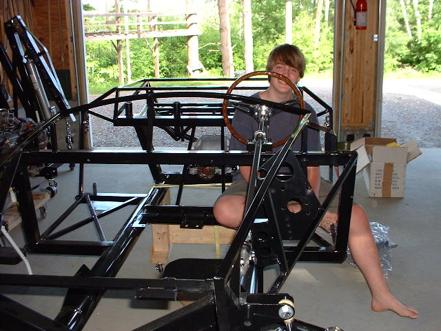
Here's a shot of the bare frame, as Nate contemplates the massive job ahead of him. Note the body buck to his right; Nate has just built it and the body is about to take up residence on it. |
|
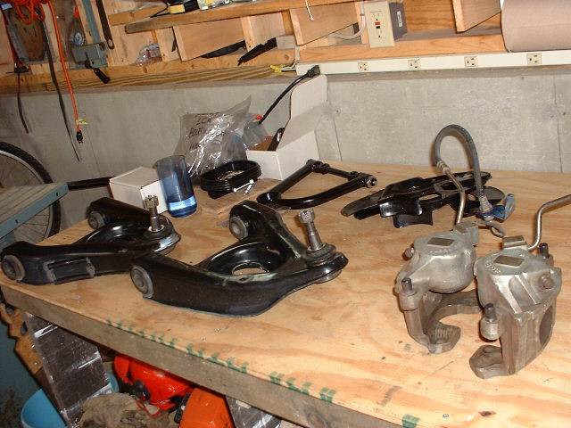
In the rear center you can also see one of the fabricated upper control arms, which come with the FFR kit, and the Mustang's brake backing plates. All the Mustang parts are in amazingly good shape. |
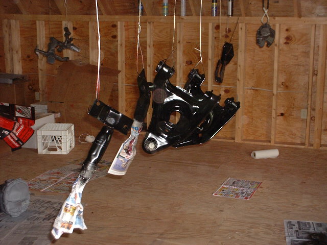 Nate has just sprayed the
Mustang parts with Eastwood Chassis Black. Don't they look great? Nate has just sprayed the
Mustang parts with Eastwood Chassis Black. Don't they look great? |
|
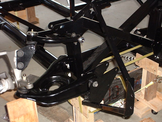
Note the upper control arm attached to the chassis at left. This is the first part we installed. |
|
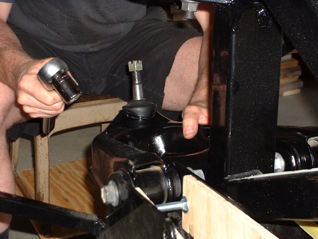
Note the pieces of plywood and the carriage bolt in the foreground. This is our first clever tool, Hine-Pennington Racing part number 00001. This tool was necessary because the ears on the frame to which the control arms attach were located too closely together, and the control arm bushings wouldn't fit in between them. The tool spreads the ears apart so we can get the control arms in. |
|
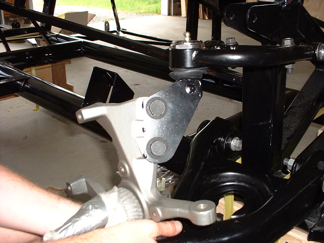
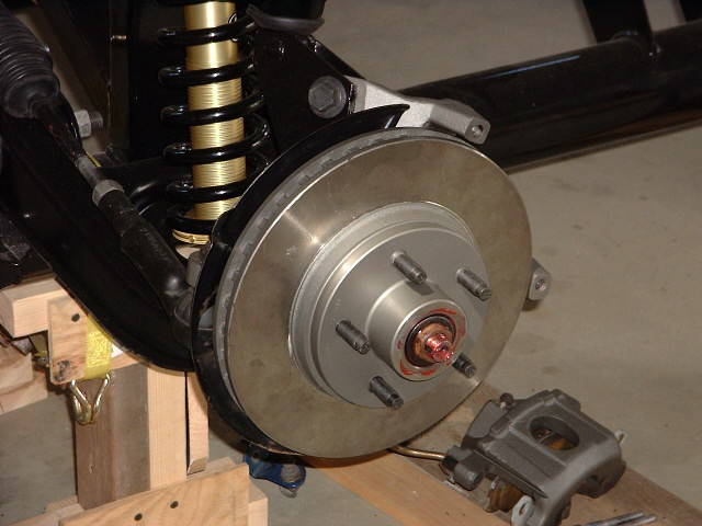
Note the bolts in the upper center of the spindle. These are part of a patented FFR idea, which uses a fabricated part to cleverly convert the Mustang strut-suspension spindle to one suitable for the Cobra's unequal-length control arm suspension. The FFR part is a welded fabrication made of heavy steel stock which simply bolts in place of the Mustang's strut and carries the upper ball joint. By the way, these bolts, which are from the Mustang, caused us a few minutes of panic, because someone (probably me) had stashed them in the garage attic, in between some wall joists, while organizing the parts stash. Later, when we needed them, we went through all the boxes but we couldn't find them (duh!). We made a panicky call to Mark Reynolds to get him to send some more. He did so, even though he was quite sure he'd shipped them. Of course, five minutes after Mark mailed the replacements, we found them. Sorry, Mark! |
|
Once we get the spring/damper unit in, we won't need ths. |
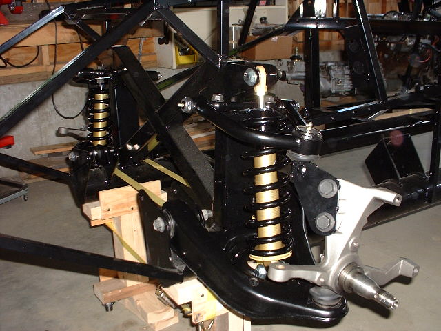 Here's a view from the left
side. Now the springs and dampers are in, and it's looking pretty
cool! Here's a view from the left
side. Now the springs and dampers are in, and it's looking pretty
cool! |
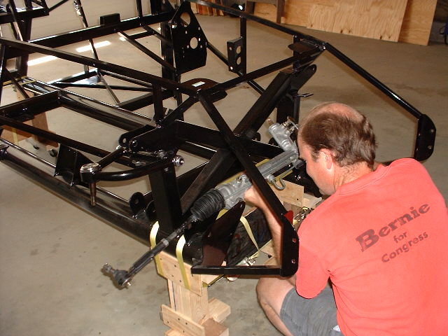
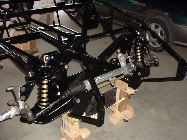 Now, finally, the steering
rack is in too! Doesn't this look totally awesome? Now, finally, the steering
rack is in too! Doesn't this look totally awesome? |
|
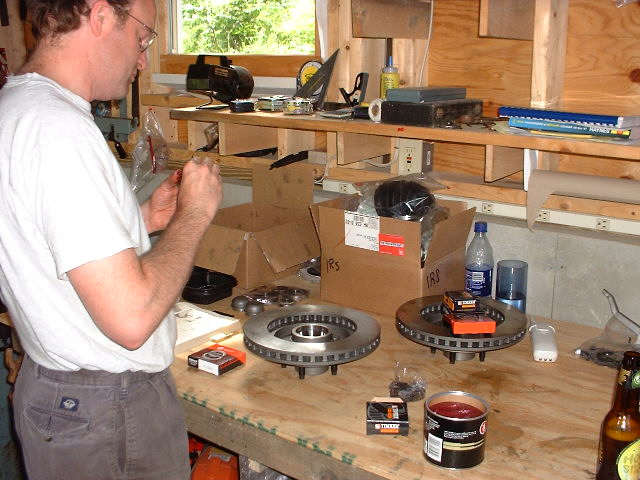
Nate carefully masked the braking surfaces on the rotors and painted the rest with Eastwood brake caliper paint, so they wouldn't turn rusty orange the first time they get wet. |
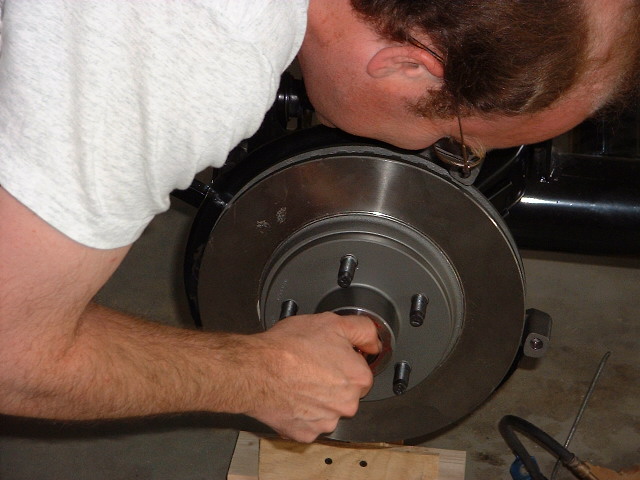 Here Nate tightens
the nut down to hold the hub/rotor to the spindle. Here Nate tightens
the nut down to hold the hub/rotor to the spindle. |
 Viola! Viola! |
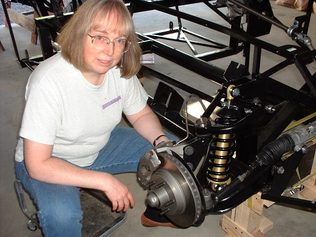 Here I am, hogging
all the glory for the front suspension assembly, at least three
quarters of which was done by Nate! Here I am, hogging
all the glory for the front suspension assembly, at least three
quarters of which was done by Nate! |
|
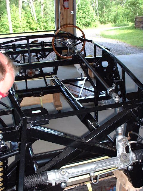
I had to space the lower pillow block out with three washers per bolt, in order to allow the middle steering shaft to clear the frame in the footbox area. And no, the steering wheel isn't supposed to be on yet, but I couldn't resist! Doesn't it look great? It sure was fun twiddling it to make the front brake discs steer! |
|
Cale helped me a great deal by sanding off the paint so the upper shaft would fit properly. We coated it with anti-seize so it wouldn't rust and become immobile later. The whole operation required Cale to assemble and disassemble the shafts and upper pillow block several times (with much tapping and clanking in the vise) until he got the right fit. Finally, after he got a good fit, Cale reinstalled the shafts and pillow block. Here you see Cale enjoying the fruits of his labor. See, didn't I tell you it was fun to have the steering wheel in place? |